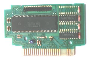
Picture of SD Snatcher PCB
Notice the two free places for the RAM ICs. They're not free any more on this one!
msxnet > Technical Info > Konami Sound Cartridge - SCC+
The Konami games Snatcher and SD Snatcher are both games on disks that operate with a cartridge, a Sound Cartridge. The cartridge is supplied with the original games.
This Sound Cartridge contains 64Kb RAM and a SCC (a sound chip designed by Konami). The RAM is not standard, so it can't be used with MemMan or any other standard program. The SCC is slightly better than the one in Konami megabit ROM cartridges. That is probably how the cartridge got the nickname "SCC+", to my knowledge Konami never used this name.
There were some rumours that the RAM in the cartridges was SRAM and the SCC was a 16 channel sound chip. As most rumours, this is not true. The RAM is just the usual DRAM (volatile) and the SCC is a 5 channel SCC. There also isn't a SCC+ in any megaROM. Several people on the MSX mailinglist have checked Solid Snake, Space Manbow, Quarth amongst others.
The two Sound Cartridges are different and incompatible. They are identical in capabilities, only the memory layout is different. So the sound chip itself is identical.
I assume Konami changed the layout so the cartridges are incompatible; if one owned Snatcher (lucky sod, nowadays) you would have to buy SD Snatcher, not just copy the disks of SD Snatcher (of course, anyone who knew Z80 assembly could `fix' that problem).
The sound chip is normal SCC (= the SCC in Konami megabit ROM cartridges) compatible. This means it can be used with cracked Konami megabit ROM cartridges for the music. Also, there is no game in the Sound Cartridge, so it doesn't need to be modified to be used (or inserted after startup).
The improvement of SCC is compared to the normal SCC that the Sound Cartridge has a extra waveform. Now channel 4 doesn't have to share its waveform with channel 5 (thus all five channels have a private waveform).
The number written on the large IC is "KONAMI 052539 SCC-I2312P001 JAPAN", which is the same number written on the Snatcher SCC+ of Klaas de Wind (I haven't opened my own Snatcher SCC+ ^^;). This shows that the sound chip of SD Snatcher and Snatcher are identical.
The sound IC is very large compared to the normal megaROM SCC IC. There are some very obvious reasons for this. First of all, to recoqnise the address BFFEh indepentently of all other addresses, all 16 address lines must be connected to it. Not all address lines are connected to a megaROM SCC IC (difference : 3 lines). The RAM is DRAM, so the address lines are multiplexed. So a seperate connect is necessary for the DRAM and the refresh signal is necessary (difference : about 11).
On the picture there are four postions for DRAM ICs. As you can see only two are used. Now there'll all filled! In the Snatcher SCC+, the other two postions are filled, that's the difference.
It's possible to add another 64Kb RAM to both cartridges. There are two open places on the print for it (see the picture above.). They're four bits wide, and have a 64K range. That's RAM IC type 4464. Note that on the RAM ICs already on-board do not have standard types printed on them.
If you've added the RAM, you can load Konami MegaROMs of 128Kb in it. It's very nice because the cartridge behaves exactly as a real SCC cartridge when it's loaded. Until you turn the power off. :) See below for the program to load unmodified .rom files.
Now all SD/The Snatchers and game collections work with your cartridge.
If you're going to do this and don't have much experience soldering: I had some trouble getting the ICs onto the PCB, because Konami was nice enough to put solder in the holes where the pins have to go in. Someone told me to use a soldering pump (also called solder sucker, tinzuigertje in Dutch) to get the solder out. Using that device it was a piece of cake.
It is possible to connect the two 64Kb memory banks so they both seems to exist (mirrored). Now values 0 - 7 selects the same memory area as values 8 - 15. This works for both cartridges.
Now all Konami games work with your cartridge, but it is not possible to load megaROMs into it.
To do this, connect the CAS (pin 16) of one of the RAM ICs with the
CAS of the places where you can put a RAM IC. Easy as can be.
Konami used the CAS (Collumn Address Strobe) as a sort of Output Enable.
The Snatcher Sound Cartridge can be used with the Konami Games Collections, since most games in these collections have been improved to use the Snatcher Sound Cartridge sound chip.
There are cracks around of SD Snatcher, The Snatcher and the Games Collections which operate with a standard megaROM SCC. Mostly the music sounds the same, but because the megaROM SCC has one wave form less, it sometimes will sound differently.
The Konami Games Collections and The Snatcher cannot be used with the standard SD Snatcher cartridge, but they can with the Snatcher cartridge. This is because they use values 0 - 7 for the bank select registers, which select the non-existing memory in the SD Snatcher cartridge so it does not seem to exist.
There are several solutions to this problem.
SD Snatcher works only with the SD cartridge. Values 8 - 15 select the memory.
Since the Sound Cartridge contains RAM, it is possible to load ROM files into it. The standard Sound Cartridge (SD or The Snatcher) can only hold ROM files up to 64Kb (that's the amount of RAM) or 128Kb if it is expanded.
If you've expanded the RAM of your Sound Cartridge, you can also load one megabit (128Kb) ROM files into your Sound Cartridge. Note that the Sound Cartridge will be behave exactly as an Konami SCC 1 megabit ROM. (until 2 ms after you turned the power off. ^_^) These ROM files can be loaded without problem, but the Konami 1 megabit ROM without SCC can also using SCROM. SCROM can convert them to use the correct mapper addresses, that's not 4000h/6000h/8000h/A000h, but 5000h/7000h/9000h/B000h). Documentation is in the zip file.
The fact that this is possible makes me think that this cartridge was used for testing Konami ROMs while they were in development. Of course, this is only speculation.
In this section I'll atempt to explain how the SCC+ can be used from assembly. It is much like a normal SCC, but now with RAM and an extra wave form.
As with Konami megaROMs, the memory is divided into four memory banks:
	Bank 1: 4000h - 5FFFh
	Bank 2: 6000h - 7FFFh
	Bank 3: 8000h - 9FFFh
	Bank 4: A000h - BFFFh
And, to access the bank select registers, write to any address of the following memory areas:
	Bank 1: 5000h - 57FFh
	Bank 2: 7000h - 77FFh
	Bank 3: 9000h - 97FFh
	Bank 4: B000h - B7FFh
As you can see this much like the megaROM SCC. See megaROM mappers for more information on memory banks and bank select registers.
Both cartridges have a (physical) memory bank of 128Kb RAM while there is only 64Kb installed on it. Thus there are 16 memory areas of each 8Kb. Bits 7 to 4 are ignored, thus 16 (10000b) selects the first memory area (0).
Here's the difference between The Snatcher cartridge and SD Snatcher cartridge: On the Snatcher cartridge, the RAM is installed in the lower part of the 128Kb (values 0 - 7 select installed RAM, 8 - F select nothing (if you read it you'll get FFh)). And on the SD Snatcher cartridge the RAM is installed in the higher part of the 128Kb: values 0 - 7 select nothing, 8 - F select installed RAM).
It is possible to add the other 64Kb RAM to both cartridges. This has several interesting advantages, see somewhere above for more information.
By default, the bank select registers have the following values:
	Bank 1: 0
	Bank 2: 1
	Bank 3: 2
	Bank 4: 3
(As, of course, a megaROM cartridge.)
This select the first 32Kb RAM in the The Snatcher cartridge, and nothing
in the SD Snatcher cartridge (unless expanded).
This is important for memory residant programs, because the 'AB' code must
be there. In the standard SD Snatcher cartridge memory resident programs
disappear (get deselected) after a hard reset.
In its initial state, you can only read from the memory. But, it wouldn't be very useful if you couldn't write to it. That's why you can change to RAM mode. In this mode, you can't change memory areas, but you can read and write to the memory (where existing). I've called the mode in which you can change memory areas "bank select mode". To change modes, use the:
Using the mode register, you can switch between normal SCC and SCC+ mode and between RAM and bank select mode.
| Bit | Function |
|---|---|
| 7 | none |
| 6 | none |
| 5 | Sound Mode (1 = SCC+, 0 = SCC) |
| 4 | Memory Mode (1 = RAM, 0 = bank select) |
| 3 | none |
| 2 | Bank 3 Mode (1 = RAM, 0 = bank select) |
| 1 | Bank 2 Mode (1 = RAM, 0 = bank select) |
| 0 | Bank 1 Mode (1 = RAM, 0 = bank select) |
The Memory Mode bit sets all memory banks to either RAM or bank select, but the Bank x Mode bits are for setting the memory banks individually back to RAM mode when the cartridge is in bank select mode. They sort of "override" the bank select mode. The Bank x Mode bits have no effect in RAM mode.
When the cartridge is in bank select mode (bit 4 low), banks 1, 2 and 3 can be set back into RAM individually using bits 0, 1 and 2.
If Bank 1 Mode is high, and the cartridge is in bank select mode (bit 4 is low), Bank 1 is put into RAM mode. The same applies to Bank 2 mode.
For the Bank 3 Mode, there is another requirement: the cartridge must be in SCC+ mode, and not SCC mode. Thus, if bit 4 is low, bit 5 high and bit 2 high, bank 3 is in RAM mode. (Mode Register value 24h for example)
So for some examples:
Value:	Bank 1   2   3   4
 10h	    RAM RAM RAM RAM
 01h	    RAM ROM ROM ROM
 27h	    RAM RAM RAM ROM
 07h	    RAM RAM ROM ROM
The Mode Register has the initial value 0: by default, it is in SCC compatibility mode and bank select mode (thus operating exactly like a megaROM cartridge).
Here are some useful values for the Mode Register (Konami uses some of these; they're holy & very logical). Note that the lower Fh could just as well be any other value, they're just there to make it obvious you want RAM mode.
| value | Memory Mode | Sound Mode |
|---|---|---|
| 00h | bankselect | SCC |
| 1Fh | RAM | SCC |
| 20h | bankselect | SCC+ |
| 3Fh | RAM | SCC+ |
The mode register can be written to via memory mapped I/O address BFFEh and BFFFh. It can't be read; if you try to read one of these addresses, you'll get a byte from the memory bank as you would have expected. It does not matter whether you use address BFFEh or BFFFh.
This, of course, has an annoying consequence: RAM at address BFFEh and BFFFh cannot be changed. Note that if you use the same RAM in a different bank, these restrictions do not apply.
When bank 3 is in bank select mode and in SCC mode, you can use the SCC in more or less the same way as the SCC in a megaROM. You must write xx11111b (3Fh, bits 6/7 do not matter) to bank select register 3. Now you can access the SCC in memory area 9800h - 9FDFh. If bank 3 is in RAM mode, you can read from the SCC but you can't write to it.
| Address | Function |
|---|---|
| 9800h - 981Fh | waveform channel 1 |
| 9820h - 983Fh | waveform channel 2 |
| 9840h - 985Fh | waveform channel 3 |
| 9860h - 987Fh | read: waveform channel 4 write: waveform channel 4 and 5 |
| 9880h - 9881h | frequency channel 1 |
| 9882h - 9883h | frequency channel 2 |
| 9884h - 9885h | frequency channel 3 |
| 9886h - 9887h | frequency channel 4 |
| 9888h - 9889h | frequency channel 5 |
| 988Ah | volume channel 1 |
| 988Bh | volume channel 2 |
| 988Ch | volume channel 3 |
| 988Dh | volume channel 4 |
| 988Eh | volume channel 5 |
| 988Fh | on/off switch channel 1 to 5 |
| 9890h - 989Fh | same as 9880h - 988Fh |
| 98A0h - 98BFh | read: waveform channel 5 (no write) |
| 98C0h - 98DFh | test register |
| 98E0h - 98FFh | no function |
This register is not used by Konami. All the addresses in the memory area (98C0h - 98DFh) refer to the same register.
| Bit | 7 | 6 | 5 | 4 | 3 | 2 | 1 | 0 |
|---|---|---|---|---|---|---|---|---|
| Function | ? | ROTATE | CNTRES | ? | ? | ? | FMLT1 | FMLT0 |
The default value is 0.
Bit 7 is either unused or repurposed for something else. At this time it is unknown what it's used for.
If ROTATE is set the waves for all channels will rotate at the speed of their channel's ftone.
The CNTRES bit will cause the wave counter for a channel to restart every time the tone value for that channel changes.
Bits 4 to 2 are probably identical to what they are on the SCC, but at the moment this is uncertain.
The FMLT bits change the frequency of all the channels. If FMLT0 is set all
the frequencies are multiplied by 256. If FMLT1 is set all frequencies are
multiplied by 16, overriding the 256 multiplication.
(Most frequencies are shifted out of hearing range, except if you set the
frequency to minimum (TP = FFFh), then you'll hear something.)
When bank 4 is in bank select mode and in SCC+ mode, you can active the SCC by writing 1xxxxxxxb (80h, bits 6 to 0 are the ROM bank) to bank select register 4. The SCC+ appears at memory area B800h to BFFDh (last two bytes are for mode register). It has the following structure, which is much like the SCC. If bank 4 is in RAM mode you can read from the SCC but you can't write to it.
| Address | Function |
|---|---|
| B800h - B81Fh | waveform channel 1 |
| B820h - B83Fh | waveform channel 2 |
| B840h - B85Fh | waveform channel 3 |
| B860h - B87Fh | waveform channel 4 |
| B880h - B89Fh | waveform channel 5 |
| B8A0h - B8A1h | frequency channel 1 |
| B8A2h - B8A3h | frequency channel 2 |
| B8A4h - B8A5h | frequency channel 3 |
| B8A6h - B8A7h | frequency channel 4 |
| B8A8h - B8A9h | frequency channel 5 |
| B8AAh | volume channel 1 |
| B8ABh | volume channel 2 |
| B8ACh | volume channel 3 |
| B8ADh | volume channel 4 |
| B8AEh | volume channel 5 |
| B8AFh | on/off switch channel 1 to 5 |
| B8B0h - B8BFh | same as B8A0h - B8AFh |
| B8C0h - B8DFh | test register |
| B8E0h - B8FFh | no function |
The difference is that now channel 5 has a private waveform. For more information about the operation of the SCC, see SCC Sound Chip.
The fact that SCC may be addressed in two modes, this does not mean that the SCC+ has twice the channels of normal SCC. If you change Sound Mode, the different addresses refer to the same registers.
If the SCC control areas (these things above) are active, and you put the SCC+ into RAM mode and then start writing to the control areas, some really weird things happen in the RAM. The SCC is unaffected but whole areas of the RAM are messed up.
BiFi <bifi@msxnet.org>